Friday, November 11, 2016

Raspberry Pi & Arch Linux - Day 18 - Noncanonical mode input and child process in Python


In this post, we will talk about two thing: (1) noncanonical mode of input and (2) child process in Python. The knowledge of the child process is not necessary for our project whereas the first is crucial. Before we can build algorithm to instruct the robot to move automatically, we first need to know how to control the robot manually. In other words, we are going to build a remote control robot car before anything else.

The idea is that we enter the command through the keyboard and once the program receives the command it controls the speed and the direction of the robot accordingly. For example, when we type the up arrow key, the robot will increase its speed or when we type the left arrow key, the robot will turn left.

There is one problem. Most of the time, the default setting of the user input is based on line. The user will enter whatever he wants and then press "return" to submit the command. However in our case, we want to enter the command char by char. We do not want to type 10 times the up arrow key plus a "return" key to tell the program that we want to quickly increase the speed of the robot.

A quick search on Google gives us the following solution.


def getchar():
   #Returns a single character from standard input
   import tty, termios, sys
   fd = sys.stdin.fileno()
   old_settings = termios.tcgetattr(fd)
   try:
      tty.setraw(sys.stdin.fileno())
      ch = sys.stdin.read(1)
   finally:
      termios.tcsetattr(fd, termios.TCSADRAIN, old_settings)
   return ch


Note that the three packages used in this function are quite low-level.

This solution has one drawback. When we call the getchar() function, it will block and wait for user to enter the character. This is not convenient when the user does not want to any command. To deal with this problem, we need to have timeout feature. We can find many solutions on this issue.  Some of the solutions uses a separate process to handle the inputs. Here we have another solution.


def getchar(timeout=3):
    fd = sys.stdin.fileno()
    old_setting = termios.tcgetattr(fd)

    try:
        # switch to noncanonical mode
        tty.setraw(sys.stdin.fileno())
        new_setting = termios.tcgetattr(fd)

        # set the timeout
        cc = new_setting[6]
        cc[termios.VTIME] = timeout # timeout = 0.3s
        cc[termios.VMIN]  = 0       # start the timer immediately

        # update termios struct
        termios.tcsetattr(fd, termios.TCSADRAIN, new_setting)

        # read
        ch = sys.stdin.read(1)
    finally:
        termios.tcsetattr(fd, termios.TCSADRAIN, old_setting)
    return ch


As we mentioned, termios is a quite low-level package. What we need is actually called the noncanonical mode of input. It is controlled in the struct termios and it does provides parameters to control the timeout behavior.

The second thing we want to cover in this post is the child process. The following code shows how we can send the interrupt signal to all the processes.


if key_press == 'q':
    print("Exiting system")
    pid = os.getpid()
    parent = psutil.Process(pid)
    children = parent.children(recursive=True)
    for process in children:
        os.kill(process.pid, signal.SIGINT)

    os.kill(pid, signal.SIGINT)

In Python, we use os package to get the current process id and send signal to a given process. The signals are defined in the signal package. To send the signals to the child processes, we need to get the child process id of a given process. This functionality is provided in the psutil package. More specifically, we use the psutil.Process(pid) to get a list of child process object of the given process id.


--END--

Sunday, October 30, 2016

Raspberry Pi & Arch Linux - Day 17 - Visualization in terminal and KeyboardInterrupt handler


Happy Halloween!


Last time, we saw that the robot car could run without any direction and speed control. To make the robot more intelligent, we should first make sure that it can interact with the environment. All the communication between the robot car and the environment go through the radar in the front of the car. It consists of a stepper motor as the base and a ultrasonic distance sensor which measure the distance to the obstacles.

As we add more components to the robot car, the number of parameters in the system increase dramatically. (probably it is a good idea to have an overview of all the parameters currently used in the robot car). Before we code the direction and speed control algorithm, it is necessary to configure all the parameters so that the robot car can function properly. The parameters of the most interests are

  • the range of the radar
  • the angle speed of the radar
  • the frequency of the sampling (radar base and distance sensor)
  • the buffer size of the data

One of the problems is how we can visualize the distance map in the terminal. There are two approaches:
  • gnuplot
  • bashplotlib in python
If we use gnuplot, we need to start a subprocess in python and sometimes it is very difficult to deal with the subprocess, especially when we want to load the outputs of the subprocess. So for our testing purpose, we choose the bashplotlib package. 

The function we use is plot_hist because the distance map is essentially a histogram. The x-axis is the degree, which indicates the position of the radar base (stepper motor); the y-axis is the distance to the obstacles. To plot the histogram, we need to convert the floating distance to int. 

I do not know if I missing something about the bashplotlib package. It seems to me that the plot_hist function only accepts the raw data, which means we can not pass a dictionary or pd.Series to it. So if you have a pd.Series 


In[4]: ts
Out[4]: 
-1    3
 0    2
 1    5
dtype: int64


You need to manually convert it to [-1,-1,-1,0,0,1,1,1,1,1].

The figures below present the plot in terminal. It is not very fancy but it is much better than looking at an array of 100 numbers. :)


To make the testing more convenient, we want the radar to go back to its zero or initial position when the process is interrupt by the ctr-c. When we enter the ctr-c, the python interpreter will raise a KeyboardInterrupt error in the "main" process and all the subprocess as well. It means that we need to handle the keyboard interrupt error in both the main script and the scripts that use multiprocessing.Process. Fortunately, all components that are running concurrently are wrapped in the ContinuousComponentWrapper. So we just need to add a exception handler in the run method of the ContinuousComponentWrapper

    # ContinuousComponentWrapper
    def run(self):
        """
        Running the component in the infinite loop. To change the status of the component, one can send command to the command queue.
        #TODO: add a stop-pill
        """
        try:

            while True:
                while not self._cmd_Q.empty():
                    cmd = self._cmd_Q.get()
                    if cmd == CMD_EXIT or cmd == (CMD_EXIT,):
                        return 
                    self._component.parse_and_execute(cmd)


                self._component.run()
                self._component.send_msg(self._output_Q)

        except KeyboardInterrupt:
            if hasattr(self._component, 'KeyboardInterruptHandler'):
                self._component.KeyboardInterruptHandler()
            print('{} property exit after KeyboardInterrupt.'.format(self._component.name))

and create a KeyboardInterruptHandler method for the DistanceRadarBaseComponent.

    # DistanceRadarBaseComponent
   
    def KeyboardInterruptHandler(self):
        self._stepper_motor.back_to_zero_pos(delay=self._delay)

--END---

Wednesday, October 26, 2016

Raspberry Pi & Arch Linux - Day 16 - First Prototype


Here comes our first prototype!

To make the project portable, we need to first find a power supply for the electronic components. The one I used is RAVPower 22000mAh 5.8A Output 3-Port Portable Charger Power Bank External Battery Pack (2.4A Input, Triple iSmart 2.0 USB Ports, High-density Li-polymer Battery) For Smartphones and more- Black

This power bank is kind of heavy and it is very stable when we put it on the chassis.

After putting everything together, with the help of lots of tapes, the robot car looks like this:


It can move quite fast. I had concerns that the loading may be too heavy to carry but motor's performance beats my expectation and shows a lot of more potential. I think I can still add a few devices to the robot.

Here is the first drive


It is obviously a milestone of the project when all the components are on the chassis. However, some technical issues come to the surface immediately. One of the main issues is the position of the distance sensor. It turns out that there is no easy way to install the sensor to the center of the chassis. In this prototype, it is installed at the right corner of the robot.


Another problem is caused by the size of the power bank. This power bank is quite large and it cannot fully fit into the space. Even worse, it actually becomes an obstacle of the distance sensor and it limits the range of scanning area. As shown in the figure above, we have blind spot on the left side of the robot car. Therefore, the left side and the right side are not longer symmetric. This factor should be taken into account in the analytical algorithm development.

--END--

Tuesday, October 18, 2016

Raspberry Pi & Arch Linux - Day 15 - Obstacle Avoidance Method (1)


Let us talk about the obstacle avoidance algorithm today.

We start from some simple ideas. Here is a paper illustrating the idea of vector field histogram:

http://www-personal.umich.edu/~johannb/Papers/paper16.pdf

The main idea is to use a two-dimentional Cartesian histogram grids to represent the environment. Each cell of grid has a certainty value which represents the confidence level in the existence of an obstacle. We can think of this grid as a probabilistic view of the obstacle location.

One of the steps in the Vector Field Histogram (VFH) approach is that we need to reduce the two dimentional Cartesian histogram grids to one-dimentional polar histogram. Honestly I do not quite understand why we need to convert from two-dimentional Cartesian system to one-dimentional polar system instead of having the polar system from the beginning. In our case, we have a rotational distance radar; hence it is very natural to work with polar system in the first place.

Here is a draft version of code that creates the polar histogram. There is nothing specially here. What we need to do is to align the data from radar motor and the data from distance sensor based on the timestamp. The data from the radar motor provides the angle of the distance sensor and the data from the sensor is just the distance. Once the timestamp is aligned, we will know the distance measured when the radar is positioned at a particular angle. And this is essentially the polar histogram.


def create_distance_map(df_radar_base, df_distance_sensor):
    """
    Create the distance map. The map represents the environment in front of the robot. It is the association between position of
    radar (in degree) and the distance detected in that position.

    Args:
        df_radar_base:      data sent from distance radar component.
        df_distance_sensor: data sent from the distance radar sensor component.

    Return:
        A pd.Series. The index is the position of the radar base and the value is the distance deteced. 

    Note:
        The map is discrete. The value of index in the retured Series is integer.
    """


    df_sensor = df_distance_sensor
    df_base = df_radar_base

    df_sensor['timestamp'] = format_timestamp(df_sensor['timestamp'])
    df_base['timestamp']   = format_timestamp(df_base['timestamp'])

    df = pd.merge(df_sensor, df_base, on='timestamp', how='outer', suffixes=('_sensor','_base')).sort_values('timestamp')
    
    # smooth the distance.
    # window = int(df.shape[0] / df['pos'].notnull().sum())
    # df['avg_distance'] = df['distance'].rolling(window=window, min_periods=1).mean()
    # df['distance'] = df['distance'].combine_first(df['avg_distance'])
    # df = df.drop('avg_distance', axis=1)

    # clean the data
    df['distance'] = df['distance'].fillna(method='ffill')
    df['status']   = df['distance'].fillna(method='ffill')

    df_work = df[(df['pos'].notnull()) & (df['distance'].notnull())]

    # select useful information
    df_work = df_work[['timestamp','status','distance','pos','degree']]


    # create the distance map
    df_work['pos_bin'] = df_work['pos'].astype(int)

    ts_distance_map = df_work.gropuby(by='pos_bin')['distance'].mean().sort_index()

    return ts_distance_map


To align the timestamp, we merge the two data frame on timestamp and then fill the NaN. In pandas-0.19, there is a new function called merge_asof and it can merge two data frames without an exact match on keys.

In the context of the VFH method, obstacles exert repulsive forces and the magnitude of the such forces depends on the distance between obstacles and the robot. All these repulsive forces form a kind of filed and this is reason why we called this method Vector Field Histogram.


VFH is a simple idea but it is that easy to implement. The algorithm actually has three steps:

  1. collect and transform data
  2. generate signal/command
  3. physical steer controllers
We will even experience difficulties for the first item for our ultrasonic sensor is a cheap one and it is not very stable. Also the measurement itself may not be accurate enough. For the second and third item, we have more serious problems. We can control the speed and the direction of the robot but we do not have any idea of the absolute speed and we loosely control the angle of the turn. 

I think the next big question is how we can continuously update the polar histogram without fine control on the speed and angle of the robot.


--END--

Sunday, October 16, 2016

Raspberry Pi & Arch Linux - Day 14 - A simple Engine class the provides high level control over two wheels


Something else distracted me last week so there was no significant progress.

It is the moment to consolidate a little bit and put all the pieces together.


To control the speed and the direction of the robot, we need to have a Engine class which defines some high level commands such as turn_left, turn_right and stop. In theory, we can decrease the speed of the left wheel and increase the speed of the right wheel to achieve the turn-left effect. We will not know if this works until we do a real test. Also for the present, I can imagine that we may need different types of turn-left operation: it can turn slowly or quickly; it can be a slight turn or a sharp turn. For now, we have scale and period parameters as placeholder.


class Engine:
    """
    Engine class controls the movement of the robot. It consists of two wheels.
    """

    def __init__(self, startup_scale=0.1, stable_scale=0.6, cmd_Q=None, output_Q=None,left_wheel_comp=None, right_wheel_comp=None):
        """
        Args:
            startup_scale:    float. It controls the start up sclae of the two wheel. 
            stable_scale:     float. It controls the speed of the wheel in the stable status.
            left_wheel_comp:  Instance of WheelComponent.
            right_wheel_comp: Instance of WheelComponent.
            cmd_Q: Do we need this?
            output_Q: Do we need this?

        Note:
            The function will construct the ContinuousComponentWrapper internally. The user of the class will not be able to control the two wheels
            directly. All the operations are performed through the Engine class.
        """
#        assert isinstance(cmd_Q, mp.queues.Queue)
#        assert isinstance(output_Q, mp.queues.Queue)

        assert isinstance(left_wheel_comp, WheelComponent)
        assert isinstance(right_wheel_comp, WheelComponent)

        self._cmd_Q = cmd_Q
        self._output_Q = output_Q
        self._left_wheel_comp = left_wheel_comp
        self._right_wheel_comp = right_wheel_comp

#        self._reference_pulse_left = left_wheel_comp.reference_pulse
#        self._reference_pulse_right = right_wheel_comp.reference_pulse
#        self._pulse_left = left_wheel_comp.pulse
#        self._pulse_right = right_wheel_comp.pulse

        self._cmd_Q_left = mp.Queue()
        self._cmd_Q_right = mp.Queue()
        self._output_Q_left = mp.Queue()
        self._output_Q_right = mp.Queue()

        self._left_wheel = ContinuousComponentWrapper(component=self._left_wheel_comp, cmd_Q=self._cmd_Q_left,output_Q=self._output_Q_left)
        self._right_wheel = ContinuousComponentWrapper(component=self._right_wheel_comp, cmd_Q=self._cmd_Q_right,output_Q=self._output_Q_right)


    def _change_speed(self, left_scale=0., right_scale=0.):
        """
        change the speed of the two wheels. A utility function.
        """
        self._cmd_Q_left.put(('increase_speed',(left_scale,), {}))
        self._cmd_Q_right.put(('increase_speed', (right_scale,), {}))


    def stop(self):
        """
        Breaks the robot. Set the wheels to be still.
        """
        self._cmd_Q_left.put(('stop', (), {}))
        self._cmd_Q_right.put(('stop', (), {}))

    def turn_left(self, scale=0.5, period=1.):
        """
        Turn left. The if scale = 0, the turn is slow; if the scale = 1., the turn is sharp.
        """
        scale = min(scale, 1)
        scale = max(scale, 0)
        left_scale = -(1 - scale)
        right_scale = scale
        self._change_speed(left_scale, right_scale)
        time.sleep(period)
        self.stop()
        self.increase_speed(self._startup_scale)


    def turn_right(self, scale=0.5, period=1.):
        """
        Turn right. The if scale = 0, the turn is slow; if the scale = 1., the turn is sharp.
        """
        scale = min(scale, 1)
        scale = max(scale, 0)

        left_scale = scale
        right_scale = -(1 - scale)

        self._change_speed(left_scale, right_scale)
        self.stop()
        self.increase_speed(self._startup_scale)


    def start(self):
        """
        Start the engine. This function will start the two wheels. 

        Note:
            The wheels are wrapped in the ContinuousComponentWrapper and they are multiprocessing.Process.
        """

        self._left_wheel.start()
        self._right_wheel.start()
--END--

Monday, October 10, 2016

Raspberry Pi & Arch Linux - Day 13 - RawDataHandler


In this post, we will present the draft version of RawDataHandler.

Based on our design, all the physical devices is represented by a Component class and it is further wrapper in a ContinuousComponentWrapper class. The communication is always handled by a multiprocessing queue and the format is defined in each concrete component class. So it is very easy to come up with a RawDataHandler class that can handle all the data and messages from different component.


class RawDataHandler:
    def __init__(self, name=None, parser=None, record_size=100):
        assert name is not None and parser is not None
        self._name = name
        self._records     = []
        self._record_size = record_size
        self._parser = parser
        self._columns = [x[0] for x in self._parser]

    def update(self, msg):
        if len(self._records) == self._record_size:
            self._records.pop(0)

        # parse the msg
        record = []
        for attr, idx in self._parser:
            record.append(msg[idx])
        self._records.append(record)
    

    @property
    def data(self):
        df = pd.DataFrame(self._records, columns=self._columns)
        df['param_name'] = self._name
        return df

The most important parameter is the parser. It tells the handler how to extract information of different field from the message.

Now we have all the pieces ready and we can perform the first test of our small ultrasonic radar.

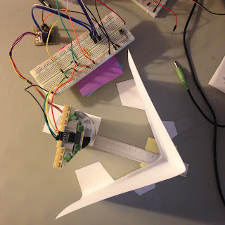
Here is the setup of the environment: we put one piece of paper in front of the radar and it forms a V-shape.


Here is the data generated by the distance sensor:


We do see a V-shape here (well...); however for some reasons, there is a gap at degree = -10. There might be two potential explanation for this phenomenon. The first one is the reflection, due the shape of the paper it is possible that the ultrasonic wave may propagate following the red line in the image. In this case, the path consists of three segments instead of two. Another possible reason is the fact that when the sensor sends and receives the signal, it is also spinning. In other words, between the time it sends the signal and it receives the signal, it will make a slight move and point to a different direction. Though this movement is relatively small because the speedo of motor is largely smaller than the speed of sound, it case it points to the corner of the V shape, the distance measured can be quite sensitive to the angle.


As we can see in the fig-1, on the left side the points lie on the a straight line as expected while on the right part we see some irregularity. I think this irregularity can be partly explained by the curvature of the paper.


Video time ^_^


--END--

Sunday, October 9, 2016

Raspberry Pi & Arch Linux - Day 12 - Build Wheel Component


In this post, we will present the code of Wheel Component.

One of the interesting problems when we try to control a wheel is the fact that the left wheel  and right wheel are mirror symmetric. It means that we cannot use the same code to control the two wheels at the same time.

For example, let us assume that we have a Motor class and it has two methods: (1)spin_clockwisely and (2)spin_anti_clockwisely. If the Motor is used in the right wheel then spin_clockwisely function will make the robot move forward while the spin_anti_clockwisely function will make the robot move backward. It is easy to see if the Motor is used in the left wheel then the effect is opposite, meaning that the spin_clockwisely function will make the robot move backward and the spin_anti_clockwisely function will make the robot forward.

In our design, we do not want the Motor class to handle the mirror symmetry problem because the motor does not know if it is used in a wheel and our Component class is specifically designed to represent a physical device. Therefore, we will create a WheelComponent to control the motor used in a wheel.


class WheelComponent(Component):
    """
    Represent a single wheel.
    """

    def __init__(self, name=None, mirror=False, pin_signal=None, repeat=10, pulse=None, width=None):
        """
        Args:
            name:           the name of the component.
            mirror:         Bool. The left wheel and right wheel is a mirro image of each other. Therefore, with the same configuration and the 
                            same operaton the effect is opposite. For example, let assume we are in a scenario where when we increase the pulse, 
                            the motor spins faster clockwisely. If this motor is used for right wheel, when the pulse is increased, the robot will
                            be speed up; while if it is used for right wheel, the robot will be slowed down. This is a mirror effect. The mirror 
                            parameter is used to handle the mirror effet so we can have a unified interface to control both the left and right wheel.
            pin_signal:     the pin number for sending the pulse to the motor.
            pulse:          the pulse that is send to the motor. If the pulse is None,it will be set to the reference pulse of the underlying motor 
                            class, which make the motor still. The default value of pulse is None.
            repeat:         the number pulse sent to the motor in a cycle.
            width:          In the communication protocol, the signal consists of two parts: (1)pulse and (2)silence. The width specifies the length 
                            of the slient period. If the width is None, it will be set to the width value of the underlaying motor class.

        """

        assert name is not None
        assert pin_signal is not None
        self._name = name
        self._pin_signal = pin_signal
        self._motor = WheelMotor(pin_signal=self._pin_signal)
        self._reference_pulse = self._motor.reference_pulse
        self._max_deviation = self._motor.max_pulse_deviation
        self._max_pulse = self._reference_pulse + self._max_deviation
        self._min_pulse = self._reference_pulse - self._max_deviation

        self._pulse = pulse if pulse is not None else self._reference_pulse
        self._width = width if width is not None else self._motor.width
        self._repeat = repeat
        self._mirror = mirror


    def run(self):
        self._motor.generate_pulse(repeat=self._repeat,pulse=self._pulse, width=0.020)

    def send_msg(self,Q):
        pass

    @property
    def pulse(self):
        return self._pulse
    @pulse.setter
    def pulse(self, val):
        self._pulse = min(val, self._width)


    @property
    def repeat(self):
        return self._repeat
    @repeat.setter
    def repeat(self,val):
        self._repeat = min(val, 50)

    def increase_speed(self, scale):
        scale = min(scale, 1.)
        scale = max(scale, -1.)

        increment = scale *  self._max_deviation

        if self._mirror:
            increment = -1 * increment

        new_pulse = self.pulse + increment
        new_pulse = min(self._max_pulse, new_pulse)
        new_pulse = max(self._min_pulse, new_pulse)

        self._pulse = new_pulse

    def stop(self):
        self._pulse = self._reference_pulse


Note that in the __init__ function ,we have a parameter called mirror and it is used in the increase_speed method. This parameter indicates if we want to use the mirror effect of an operation. In case of increasing the speed of the rotation, it flips the sign of the incremental amount of pulse. In this way, we have a unified interface to control both the left and right wheel.

To use the component, we need to wrap it in a ContinuousComponentWrapper as we did before. Here is a sample code that shows how we can increase the speed of the wheel.


pin_signal_left = 13
pin_signal_right = 15

left_wheel_component  = WheelComponent(name='left_wheel', mirror=False, pin_signal=pin_signal_left, repeat=20, pulse=None, width=None)
right_wheel_component = WheelComponent(name='right_wheel', mirror=True, pin_signal=pin_signal_right, repeat=20, pulse=None, width=None)

cmd_Q_left_wheel     = mp.Queue()
output_Q_left_wheel  = mp.Queue()
cmd_Q_right_wheel    = mp.Queue()
output_Q_right_wheel = mp.Queue()


left_wheel  = ContinuousComponentWrapper(component=left_wheel_component,cmd_Q=cmd_Q_left_wheel,output_Q=output_Q_left_wheel)
right_wheel = ContinuousComponentWrapper(component=right_wheel_component,cmd_Q=cmd_Q_right_wheel,output_Q=output_Q_right_wheel)


left_wheel.start()
right_wheel.start()

scale = 0.
while True:
    print('scale: {}'.format(scale))
    time.sleep(3)
    cmd_Q_left_wheel.put(('increase_speed',(0.1,), {}))
    cmd_Q_right_wheel.put(('increase_speed', (0.1,), {}))
    scale += 0.1
--END--

Saturday, October 8, 2016

Raspberry Pi & Linux Arch - Day 11 - Build the Ultrasonic Radar


In this post, we will show how we combine the stepper motor and the ultrasonic sensor together to make a simple ultrasonic radar.

To combine the motor and the sensor together, it is essential to establish communications between them. Our design is to connect all the devices to a central controller and it will handle the communications among components holistically.


As we mentioned earlier, the components work in a parallel way so we need to use the multiprocessing module in python. When we write the code to control a device, we need to implement two functionalities: (1) code that controls the physical device and (2) code that handle the communication between different components and processes.

We have already seen the code that controls the physical device. StepperMotor class and DistanceSensor are two examples. They are sufficient if we just want to make the device work; however if we want to establish communication between devices and dynamically change the parameters of the device, we need new code.

Here, we will create a new class called Component to represent each physical component in the robot. The Component class defines an interface and provides basic functions that allows the physic device to run and to communicate.


class Component(metaclass=ABCMeta):
    #TODO: add lock to component to make it safer
    @abstractmethod
    def send_msg(self,Q):
        """
        Send the message to the Q. Q should support put operation.
        Note that message is not incluced in the parameter list, it is the 
        responsibility of class to implement the process.
        """
        pass

    @abstractmethod
    def run(self):
        """
        Upon calling this function, the component will perform its routine work.
        """
        pass

    def parse_and_execute(self, msg_tuple):
        """
        This function will parse the arguments and call the member function accordingly.
        The msg_tuple should be (func_name, args, kwargs):
            func_name : the name fo the member function that will be called
            args      : the argument list. It is also a tuple.
            kwargs    : keyword argumetns. It is a dictionary

        """

        func_name, args, kwargs = msg_tuple
        func = getattr(self, func_name)
        func(*args, **kwargs)

    def update(self, attr, val):
        setattr(self, attr, val)

    def d_update(self, attr, val):
        orig_val = getattr(self,attr)
        setattr(self, attr, orig_val + val)

    @property
    def name(self):
        return self._name

    @property
    def parser(self):
        return self._parser


Note that all the communication is handled by multiprocessing.Queue. It is the bridge between a component and the central controller (we will talk about the controller later).

Let us write some codes to create sensor component:

class DistanceRadarSensorComponent(Component):
    PARSER = [(x,i) for i,x in enumerate(['timestamp','comp_name','distance', 'status'])]
    def __init__(self, name=None, pin_echo=None, pin_trig=None, unit='m', delay=0.00001):
        assert name is not None

        self._name = name
        self._sensor = DistanceSensor(pin_echo=pin_echo, pin_trig=pin_trig, unit=unit)
        self._measure_result = (None,DistanceSensor.INIT)
        self._delay = delay

        self._parser =  DistanceRadarSensorComponent.PARSER

        super(DistanceRadarSensorComponent,self).__init__()

    def run(self):
        self._measure_result = self._sensor.measure()
        time.sleep(self._delay)

    def send_msg(self,Q):
        res = self._measure_result
        msg = (time.time(), 'DistanceRadarSensor::{}'.format(self._name), res[0], res[1])
        Q.put(msg)

Nothing special here. As mentioned in the comments, we need to put the routine work in the run() method and for the distance sensor, the routine work is of courser to measure the distance. The send_msg method defines which information we want to send back to the controller.

As you can see, the Component class has nothing to do the multiprocessing and it cannot work continuously. Though we can call the component.run() is a while loop, we wipe out the possibility to communicate with the component not to mention to control the device dynamically.

To solve this problem, we will write a kind of decorator that wraps a component and make it possible to communicate with other components and run continuously.


class ContinuousComponentWrapper(mp.Process):
    """
    The ContinuousComponentWrapper is use to make a component running in the background.
    

    Args of __init__:
        component: an instance of component class.
        cmd_Q:     command queue. It is used to send command to the component when it is running in the background.
        output_Q:  output queue. The wrapper sends out message or informaiton through this queue.


    """
    def __init__(self, component=None, cmd_Q=None,output_Q=None):
        assert isinstance(component, Component)
        assert isinstance(cmd_Q, mp.queues.Queue)
        assert isinstance(output_Q, mp.queues.Queue)

        self._component = component
        self._output_Q = output_Q
        self._cmd_Q = cmd_Q
        super(ContinuousComponentWrapper,self).__init__()

    def run(self):
        """
        Running the component in the infinite loop. To change the status of the component, one can send command to the command queue.
        #TODO: add a stop-pill
        """
        while True:
            while not self._cmd_Q.empty():
                cmd = self._cmd_Q.get()
                self._component.parse_and_execute(cmd)

            self._component.run()
            self._component.send_msg(self._output_Q)


    @property
    def component(self):
        return self._component


A flow chart helps us understand the structure better:


In the run() method, we have a while loop that makes the component run continuously. At the beginning of each loop, we first check if the component receives new command. The command is sent through the cmd_Q (command queue). If we do have new commands, the component will parse the command and execute it. In general, the command is used to change the parameters of the underlying component and it is in this way we can control the physical device dynamically. After the component finishes the run, it will send message through the output_Q (output queue).  Most of the time, the output_Q is connect to the controller. As you can see here, it is really the cmd_Q and the output_Q that define the scope of the component. 


The next step is to write a DataHandler class that can deal with output messages from different components. We are now close to the moment to create the "brain" of the robot and it really seems exciting.


--END--

Monday, October 3, 2016

Raspberry Pi & Arch Linux - Day 10 - Camera Module


We have two news for today; one is good and one is bad. Let us start with the bad one...

In the previous post, we mentioned that we can use coroutines in Python to handle the communication between different components. It turns out that it makes no sense because at the end of the day, we still need to explicitly invoke the function by sending a message to the generator, which is essentially equivalent to calling the function directly.

The problem still remains. How can  we handle the communication between different components? Looking into the details, the radar motor spins while the distance sensor constantly measures the distance. The motor needs to send back the data of its position and the sensor sends back the distance to the obstacles. They are in parallel. I guess at this point, we definitely need to go with multiprocessing in Python. Surprisingly, raspberry pi has 4 cores and I really cannot understand how they can sell it for $25. Amazing achievement.

The good news is I finally manage to install the cameral module and now my raspberry pi can open its eyes and see the world for the first time.

The module we use is Raspberry PI 5MP Camera Board Module.


We also use the LEGO bricks to build a frame that holds the camera module. It is possible to connect this frame to a motor but for now we will focus on the camera itself.

Here is a tutorial (from the internet) to connect the cable to the raspberry pi.

There is a Python API for the camera module: picamera. We can install it with pip.

Before trying to test it in python, we may need to take a look at the wiki page:
https://wiki.archlinux.org/index.php/Raspberry_Pi#Raspberry_Pi_camera_module

The page provides solutions to common errors often encountered when working with the camera. A very important thing: double check the connect of the cable. If the cable is not connected correctly, the camera will not be detected.

To see if the camera works properly, take our first picture:
$ raspistill -o first-sight.jpg

If you get an error saying that the camera is not detected, you need to check the connection and reboot the raspberry pi.

Note that with the LEGO frame the picture is upside-down.  lol.....

--END--

Sunday, October 2, 2016

Raspberry Pi & Arch Linux - Day 9 - Code that controls the distance sensor


Let us go back to the distance sensor again. We haven't spent too much time on it.

For our project, we use the Ultrasonic Ranging Module HC - SR04. It is cheap and easy to work with.  For more details about the sensor, here are two useful links:
The first link is highly recommended.

The sensor has four pins: (1)Ground;(2)Vcc;(3)Trig;(4)Echo. The first two pins are easy to understand. (1) need to be connect to ground and (2) provides the power to the sensor. 5V is in the working voltage range so we can connect the power pin of raspberry pi to the sensor directly. 

(3) is the input pin of the sensor. Once the sensor receives the input pulse, it sends out ultrasonic wave. Let T denote the time between the sensor sends out the wave and the time it receives the echo. After the sensor receives the echo, it will generate an output pulse in the Echo pin that lasts T (s). Therefore, the distance is 0.5 * speed_of_sound * T.

Before we talk about the code,  we should point out that the original structure mentioned in the previous posts is not strong enough to hold the sensor when we connect the wire to the sensor. If the sensor is not strictly locked, the measures will have too much noise and will not be accurate enough to provide useful information. So we need to make some enhancements and here is the result:


The code is not hard to write if we only measure the distance once. The problem is that we want to create a kind of "radar" that can scan the space in front of the car. It means that the sensor need to continuously measure the distance and send back the results. Let us assume that we have a function called measure_once which allows us to perform a single measure. If we simply put this function in a while loop, it will not work because in that case the sensor can no longer send back the results. 

Fortunately, there is one solution to this problem: Coroutine.

For more details about Coroutine in Python, I highly recommend the online tutorial: 
A Curious Course on Coroutines and Concurrency by David Beazley. The version of Python used in the tutorial is 2.7 but almost everything can work directly in Python 3. It seems that python 3 has a package called asyncio dedicated to the tasks and coroutines. It maybe a good idea to check the official documentation later.

Here is the first version of the code: 


import RPi.GPIO as gpio
import time

#gpio.setmode(gpio.BCM)
gpio.setmode(gpio.BOARD)


class DistanceSensor:
    SUCC    = 'SUCC'
    INIT    = 'INIT'
    TIMEOUT = 'TIMEOUT'
    FAIL    = 'FAIL'

    def __init__(self, pin_echo=None, pin_trig=None, unit='m'):
        assert pin_echo is not None and pin_trig is not None
        self._pin_echo = pin_echo
        self._pin_trig = pin_trig

        gpio.setup(pin_echo, gpio.IN, pull_up_down=gpio.PUD_DOWN)
        gpio.setup(pin_trig, gpio.OUT, initial=0)
        time.sleep(1.)

        self._pulse = 0.00001
        self._status = DistanceSensor.INIT
        self._latest_measure = (None, DistanceSensor.INIT)

    def measure_once(self):
        """
        measure the distance once. The returnd value is (distance, status)
        """

        # send out the signal
        gpio.output(self._pin_trig, 1)
        time.sleep(self._pulse)
        gpio.output(self._pin_trig, 0)

        start = time.time()
        _start = start

        while gpio.input(self._pin_echo) == 0: # no echo signal received
            if time.time() - _start > 1.:
                self._status = DistanceSensor.TIMEOUT 
                break
            start = time.time()

        if self._status == DistanceSensor.TIMEOUT:
            return None, self._status

        while gpio.input(self._pin_echo) == 1: # receiving the echo signal
            stop = time.time()


        distance_m = 170. * (stop - start)

        # sanity check
        if distance_m < 0.04 or distance_m > 4:
            self._status = DistanceSensor.FAIL
            distance_m = None

        else:
            self._status = DistanceSensor.SUCC

        return distance_m, self._status

    def measure(self, delay=0.1):
        """
        Measure the distance several times. The Measure function will return a coroutine.
        """
        try:
            while True:
                msg = (yield)
                self._latest_measure = self.measure_once()
                time.sleep(delay)
        except GeneratorExit:
            print('disconnect to the distance sensor')
            pass


if __name__ == '__main__':
    echo = 18
    trig = 16

    distance_sensor = DistanceSensor(pin_echo=echo, pin_trig=trig)

    input('press any key to start')

    #print(distance_sensor.measure_once())
    observer = distance_sensor.measure(repeat=30)
    next(observer)
    
    res = []

    for msg in ['m','m','m','stop']:
        observer.send(msg)
        res.append(distance_sensor._latest_measure)

    observer.close()

    for item in res:
        print(item)


--END--

Saturday, October 1, 2016

Raspberry Pi & Arch Linux - Day 8 - Auto Start Service and Servo Motor


Problem 7: How to add netctl service to the init process in Arch Linux

Before talking about the new progress on the AutoCar project, we need to solve a very specific problem. Though we can connect to the home wifi after login, it is quite inconvenient. Is there a way to connect to wifi in the init process?

Usually, we can put init script in /etc/init.d folder or /etc/rc.d. But Arch Linux does not have such folders.


According to ArchLinux Wiki, Arch Linux uses a modern alternative called systemd to handle the init scripts. For more details, please refer to the wiki link.

There are two steps to auto start the netctl service:


Step 1: netctl enable network-profile
$ netctl enable your-network-profile
This steps will create a unit file of your profile. You can check the /etc/systemd/system folder.


The format looks like netctl@your-profile-name. There are some strange characters in the filename. The problem is that if there is "-" in the profile file name, the unit file will convert it to the hex value (\x2d). This issue is reported here and it is not a bug. 


Step 2: enable netctl service
$ systemctl enable netctl
This step creates a unit file for netctl.service in the /etc/systemd/system/multi-user.target.wants folder.


Raspberry Pi & Servo Motor

Now we can give a update of the AutoCar. We are now able to move the wheel (finally). However, this time, we use part of the Parallax 32500 ActivityBot Robot Kit
  • wheel and tire
  • high speed servo motor
  • robot chassis
  • battery holder (currently not in use)

The high speed servo motor allows us control the speed and direction of the motor, which is essential to us because we want to adjust the speed and direction of the robot based on the distance to the obstables.

The documentaion of the high speed servo motor can be found here. Essentially, we can use the output pin of raspberry pi to send signal to the motor. The communcation protocol is that if we send 1.5ms pulse to the motor and have a 20ms pause between pulses, the motor will be still and this is called the "central position". If the pulse's duration is longer than 1.5 ms, the motor spins anti-clockwisely; if the pulse's duration is less than 1.5ms, the motor spins clockwisely.


The raspberry pi's 5V voltage lies in the range of the voltage required to drive the motor and the input(signal) voltages.

Note that for some reasons, the central position is not exactly 0.0015ms pulse. It turns out to be 0.00145 in my case. 

The wiring part is quite straightforward and the official documentation is very clear and easy to understand.


Finally, the video!


x


Thursday, September 29, 2016

Raspberry Pi & Arch Linux - Day 7 - Stepper Motor


Today, we made significant progress: we set up the rotational radar mentioned in the structure last time.

The basic components of the rotational radar are:


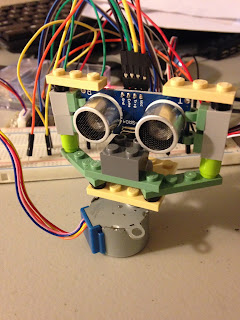
To connect them together, we will need some LEGO bricks. The final structure looks like this:


Before we move forward, we have to have some basic understanding of the stepper motors. There are very good documentations and posts online, here is a list of them:


With the driver board, wiring is very easy. Just keep in mind that the motor and the raspberry should share the same Ground. The raspberry pi 5V pin should be able to driver the motor without any issues. If your motor vibrates but not spins, you may check:

  • the setting of speed is not too fast or too slow. If the speed is set too high, the motor will fall behind the control signal; if the speed is set too low, then movement of the motor is not visible.
  • the step sequences are wrong.

The notion of speed (step angle, revolution) and step sequences can be found in the linked above. The speed is controlled by setting the delay between to two output signals.

I attached my code here. If you want to use the code, make sure you update the pin number.


import RPi.GPIO as gpio
import time

gpio.setmode(gpio.BOARD)


in_1 = 3
in_2 = 5
in_3 = 7
in_4 = 11


# set all motor input to 0
gpio.setup(in_1, gpio.OUT, initial=0)
gpio.setup(in_2, gpio.OUT, initial=0)
gpio.setup(in_3, gpio.OUT, initial=0)
gpio.setup(in_4, gpio.OUT, initial=0)


time.sleep(1.5)


def rotate(pins, degree=None, clockwise=False, delay=0.002):
    if clockwise:
        in_1, in_2, in_3, in_4 = pins[::-1]
    else:
        in_1, in_2, in_3, in_4 = pins

    if degree is None:
        remaining = 1
    else:
        remaining = degree
    
    print(in_1,in_2,in_3,in_4)

    stepsize = 360. / 4096.  * 8
    while degree is None or remaining > 0:
        print('remaining: {}'.format(remaining))
        gpio.output(in_1, 1); time.sleep(delay); 
        gpio.output(in_4, 0); time.sleep(delay); 
        gpio.output(in_2, 1); time.sleep(delay); 
        gpio.output(in_1, 0); time.sleep(delay); 
        gpio.output(in_3, 1); time.sleep(delay); 
        gpio.output(in_2, 0); time.sleep(delay); 
        gpio.output(in_4, 1); time.sleep(delay); 
        gpio.output(in_3, 0); time.sleep(delay); 
        remaining -= stepsize

def swing(pins, degree=180, delay=0.002):
    while True:
        rotate(pins, degree=degree, clockwise=True,delay=delay)
        for pin in pins:
            gpio.output(pin,0)
        time.sleep(3 * delay)
        rotate(pins, degree=degree, clockwise=False,delay=delay)
        for pin in pins:
            gpio.output(pin,0)
        time.sleep(3 * delay)

if __name__ == '__main__':
    print("starat")
    time.sleep(2)
    pins = [in_1, in_2, in_3, in_4 ]
    #rotate([in_1, in_2, in_3, in_4], degree=360)
    swing(pins, degree=180)


Here is the video:


The next step is to connect the distance sensor to raspberry pi and write code to process the data.